CALVIN MOON

Our
Project
A few years back, I participated in a toxicology lab in South Korea. In the lab, I found myself and graduate students spending a significant amount of time on repetitive pipetting. This felt like a waste of precious labor and time. So, I asked “why can’t we just buy a robot to do it for us?” The reply was quite simple. “Because it’s expensive.” Upon this reply, me and my partner* embarked on a journey to build a cheap automated liquid handler.
Currently, we are organizing a research paper to submit to the International Journal of High School Research.
*I wanted to acknowledge the help of my brother, Jeffrey Moon, in the process of constructing this device. His understanding in engineering, circuits, and computer science was essential in the process of building this device.
Automated Liquid Handler Project
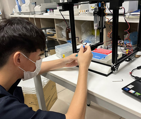
Making the first version involved a lot of trial and error. Without a clear
path to follow, we made and discarded several versions. I learned how to use Autodesk Fusion 360 to design components and print parts via stl files on a 3D printer. The printed parts were attached on a Axidraw v3 machine and each served for connection, pipette substitution, piston pressure, and tip ejection. For the basis of the model we used the Axidraw v3 for the XY movement. The EBB driver board, the main board of the Axidraw v3, required additional power supply to supply enough current to the additionally attached servo motors. Using six 1.5 V batteries and using a regulator to reduce the current to the recommended level, an adequate amount of current was supplied to the board and this was our first result.

Discard First Prototype
However, it was realized that the first prototype had to be discarded. The EBB driver board, even with the amendments, could not supply enough current to the servo motors and thus resulted in the impairment of Z axis movement. Because further application was impossible with the limitations of incorporating Axidraw V3, a different approach was needed.

Second Prototype
This time, we decided to build everything from scratch. After discussing designs and running simulations to find a plausible version, the first sketches were made. A CNC shield V3 was used to handle the signals and currents required for the motors. The AC/DC SMPS was selected as the power supply for its correct voltage and current range for the required motors. The servo motor presses the piston on the pipette. The ‘H-bot’ design was implemented for XY movement using printed rings and a toothed rubber band. A stepper motor with a shaft coupler was connected to a lead screw for Z-axis movement. Arduino IDE was used for programming and conveying signals to the main board. Through trials, errors, and adjusting coordinations, finally we had a working product that could be programmed for a specific course of actions.

Assessing the Liquid Handler
The accuracy and precision of the prototype was assessed by a test for their systematic and random error in the pipetting process. Liquid handling was performed with the machine and the resulting change in weight was measured with a microscale that could measure up to 0.001 gram (g) of difference. For the measurement of the random error, the average mass was measured and all data was inserted to find the standard deviation. 1 standard deviation or sigma (ơ) away from the data average was defined as the random error of the pipette. For the systematic error, the percent deviation of the data average from the theoretical yield was measured. The theoretical yield was 10 µL or 10 mg and the values were deducted from the theoretical yield and organized. The throughput of the system was measured by programming a time counter for the model.